
Introduction
Cracking during machining is usually a symptom of problems that began much earlier in the valve body casting process, from alloy control and solidification behavior to residual stress, geometry, and cutting conditions. Instead of treating these fractures as random shop-floor failures, it helps to trace how hidden weaknesses are exposed when material is removed. This article explains the most common causes of machining cracks in valve body castings, how to distinguish them from original foundry defects, and which process adjustments can reduce scrap, improve consistency, and protect pressure-boundary integrity before parts reach final inspection.
Why Valve Body Castings Crack During Machining
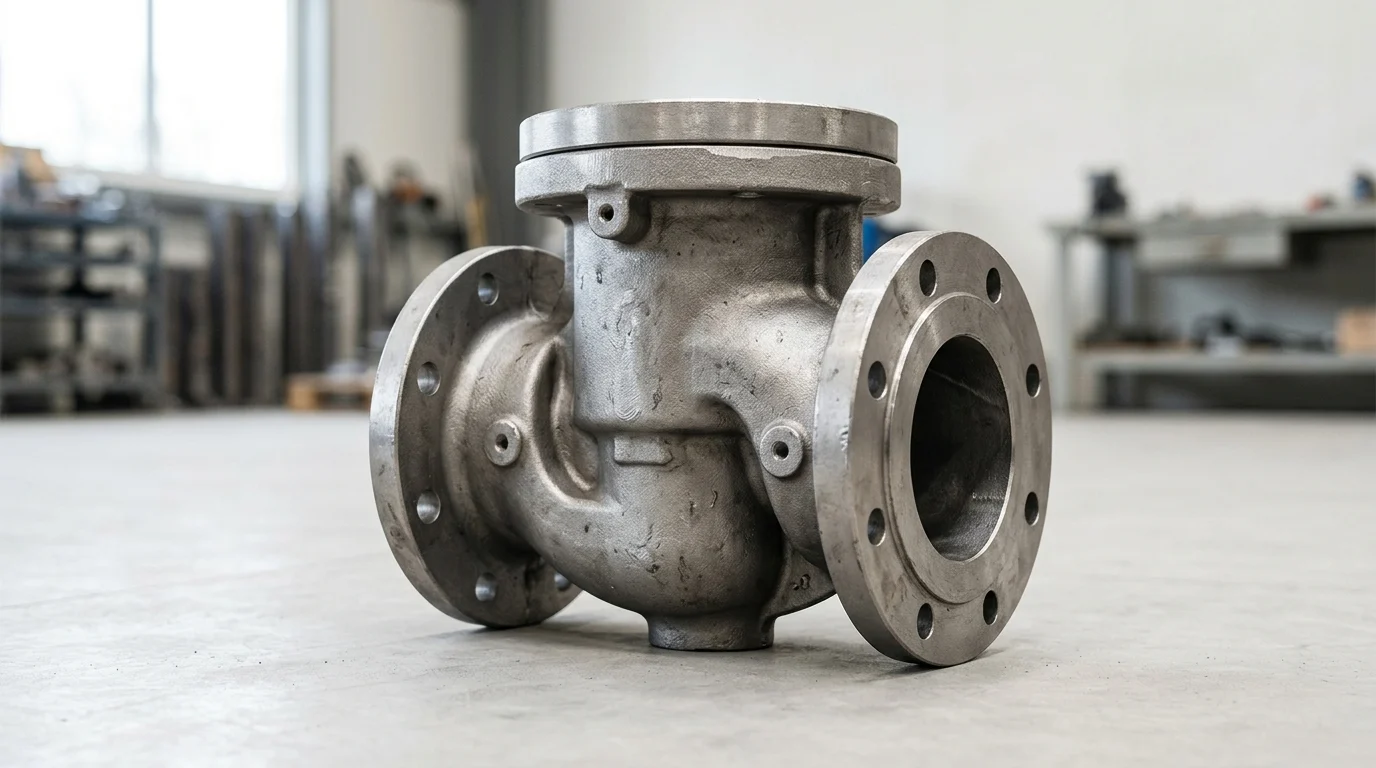
Producing a high-integrity valve body casting requires precise control over both metallurgical properties and mechanical processing. However, manufacturers frequently encounter a critical failure mode during secondary operations: cracking. When a casting fractures during or immediately after machining, it indicates a severe mismatch between the material’s structural limits and the stresses applied by cutting tools. If left unaddressed, these failures can drive batch scrap rates up to 15-20%, severely impacting production timelines and profitability.
How to Define Machining Cracks
Accurately identifying machining cracks requires distinguishing them from primary foundry defects like hot tears or cold shuts. A true machining-induced crack typically presents as a clean, bright fracture surface, indicating that the separation occurred after the metal completely cooled and during the mechanical removal of material. In contrast, hot tears exhibit oxidized, dark surfaces because they form at elevated temperatures during the solidification phase. Secondary machining cracks often originate at stress concentrators, such as sharp internal corners, intersecting machined bores, or areas where wall thickness transitions abruptly. Micro-fissures invisible to the naked eye can propagate rapidly under the dynamic loads of a milling cutter or lathe tool, eventually compromising the entire pressure boundary of the valve.
Why Cracks Increase Scrap
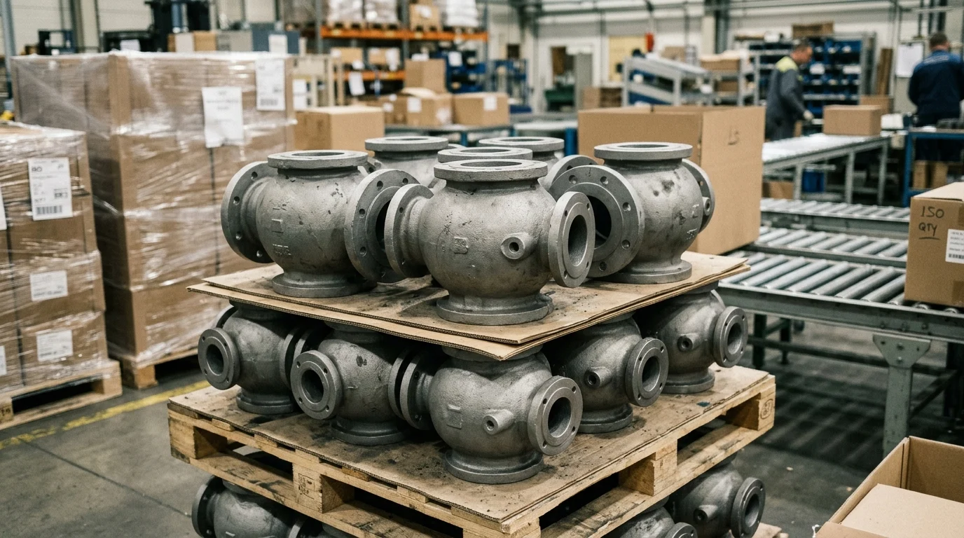
The economic impact of discovering a crack during the machining phase is exceptionally high. Unlike defects identified at the raw casting stage—where the material can simply be melted down and recycled with minimal loss—a machined casting carries accumulated value. By the time a valve body reaches the CNC machine, it has already absorbed costs related to pattern making, molding, pouring, fettling, and heat treatment. Consequently, scrapping a component at this late stage incurs a financial penalty often 300% to 500% higher than scrapping raw foundry output. Furthermore, undetected micro-cracks that survive machining but fail during hydrostatic pressure testing can lead to costly field failures, product recalls, and severe damage to a manufacturer’s reputation.
Root Causes of Machining Cracks
The initiation of fractures during mechanical processing is rarely the result of a single isolated error. Instead, it typically stems from a combination of latent metallurgical weaknesses and aggressive manufacturing parameters that push the material beyond its ultimate tensile strength.
Material and Casting Defects
Metallurgical inconsistencies form the foundation of most structural failures. High levels of residual stress are a primary culprit; if a casting cools unevenly, internal stresses remain locked within the matrix. When a cutting tool removes material, this internal equilibrium is disrupted, causing the residual stresses to release violently and fracture the part. Additionally, chemical composition plays a critical role. For example, in carbon steel valve bodies, a Carbon Equivalent (CE) exceeding 0.43% drastically reduces ductility and increases brittleness, making the material highly susceptible to fracturing under cutting pressure. Subsurface defects, such as micro-shrinkage porosity or non-metallic inclusions, act as stress multipliers. When a tool bit intersects these weakened zones, the localized stress easily exceeds the material’s fracture toughness.
| Defect Category | Specific Root Cause | Impact on Machinability | Typical Threshold for Failure |
|---|---|---|---|
| Metallurgical | Excessive Carbon Equivalent | Induces brittleness and hard spots | CE > 0.43% in standard carbon steel |
| Structural | Unrelieved Residual Stress | Causes warping and sudden fracture | Stress > 30% of Yield Strength |
| Mechanical | Excessive Clamping Force | Distorts thin-walled sections | Fixture pressure > 15 MPa |
| Operational | High Feed Rates / Dull Tools | Generates excessive localized heat | Cutting temperatures > 600°C |
Machining and Fixturing Factors
Even structurally sound components can fail if subjected to improper fixturing and aggressive cutting parameters. Hydraulic clamps used in modern CNC machining centers generate immense pressure to secure heavy components. If clamping forces exceed 15 MPa on thin-walled sections of a valve body casting, the metal can elastically deform. Once machining is complete and the clamps are released, the material attempts to spring back to its original shape, tearing the newly machined surfaces. Furthermore, using dull cutting tools or excessive feed rates generates extreme localized heat and mechanical shock. Cutting speeds above 120 m/min on hardened steel alloys without adequate coolant can cause thermal shock, initiating micro-cracks at the tool-workpiece interface that propagate deep into the valve wall.
Diagnosis and Prevention

Mitigating the risk of structural failure demands a comprehensive quality management strategy that bridges the gap between the foundry floor and the machine shop. By implementing stringent diagnostic protocols and adaptive process controls, manufacturers can eliminate the variables that lead to part rejection.
Inspection and Root Cause Analysis
Effective root cause analysis relies on deploying advanced Non-Destructive Testing (NDT) methodologies before and after mechanical processing. Magnetic Particle Inspection (MPI) and Dye Penetrant Testing (PT) are critical for identifying surface and near-surface anomalies. Modern PT formulations can detect surface flaws down to 0.02 mm in width, ensuring that micro-fissures are caught before they propagate. For internal integrity, Ultrasonic Testing (UT) and Radiographic Testing (RT) are employed to map subsurface porosity and inclusions that might later intersect with a machined bore. When a crack is detected, metallurgical cross-sectioning and Scanning Electron Microscopy (SEM) are utilized to analyze the fracture mechanics, determining whether the failure was initiated by a brittle inclusion, thermal shock, or mechanical overload.
Corrective Actions and Process Controls
Implementing corrective actions requires optimizing both the material conditioning and the mechanical processing parameters.
Key Takeaways
- The most important conclusions and rationale for valve body casting
- Specs, compliance, and risk checks worth validating before you commit
- Practical next steps and caveats readers can apply immediately
Frequently Asked Questions
How can I tell if a valve body casting crack happened during machining?
Machining cracks usually show a clean, bright fracture surface. Hot tears from casting are darker and oxidized. Check sharp corners, bore intersections, and wall-thickness transitions first.
What is the most common material cause of cracking in valve body casting machining?
Residual stress is a leading cause. Uneven cooling or poor stress relief leaves stress locked inside the casting, which can release suddenly when material is removed.
Can chemical composition make a valve body casting crack more easily?
Yes. In carbon steel valve bodies, a Carbon Equivalent above about 0.43% can reduce ductility and create brittle zones that crack under cutting loads.
How can fixturing cause a valve body casting to crack?
Excessive clamping can distort thin sections and concentrate stress. Use balanced support, lower clamping pressure, and fixtures that match the casting geometry.
What practical steps reduce cracking during valve body casting machining?
Verify stress-relief heat treatment, inspect for subsurface porosity, avoid dull tools, reduce feed and heat, and soften sharp internal corners in the casting design.